Getting Started with VMware Tanzu SQL with MySQL for Kubernetes

Let’s deploy Tanzu SQL with MySQL on Kubernetes and use phpMyAdmin to interact with our
database secured with TLS

VMware Tanzu SQL with MySQL for Kubernetes is quite a mouthful. For this post, I’ll refer to the product as Tanzu SQL/MySQL. We’re going to deploy it onto an existing Tanzu Kubernetes Grid cluster.

Objectives:

  • Deploy Tanzu SQL with MySQL on Kubernetes
  • Use phpMyAdmin to interact with our databases
  • Secure database instances with TLS

Cluster Setup

Tanzu SQL/MySQL can run on any conformant kubernetes cluster, if you already have one running, you can skip ahead. If, like me, you want to provision a new TKG cluster for Tanzu SQL/MySQL, you’ll want settings like this:

  • K8s version 1.18 or 1.19 or 1.20.7
  • Additional volume on /var/lib/containerd for the images
  • For a test cluster, best-effort small control-plane nodes (3) and best-effort-medium worker nodes (2) is sufficient to start, YMMV.
  • Install metrics-server and add appropriate PSPs

Get the images and chart

You’ll need to login to pivnet and registry.pivotal.io, accept the EULA for VMware Tanzu SQL with MySQL for Kubernetes.

At a command-line, run:docker login registry.pivotal.io then, provide your credentials. This is so that docker can pull down the images from VMware. Login to your local container registry as well – you’ll need permissions to push images into your project.

In the following commands, replace “{local repo}” with the FQDN for your local registry and “{project}” with the project name in that repo that you can push images to.

docker pull registry.pivotal.io/tanzu-mysql-for-kubernetes/tanzu-mysql-instance:1.0.0
docker pull registry.pivotal.io/tanzu-mysql-for-kubernetes/tanzu-mysql-operator:1.0.0
docker tag registry.pivotal.io/tanzu-mysql-for-kubernetes/tanzu-mysql-instance:1.0.0 {local repo}/{project}/tanzu-mysql-instance:1.0.0
docker tag registry.pivotal.io/tanzu-mysql-for-kubernetes/tanzu-mysql-operator:1.0.0 {local repo}/{project}/tanzu-mysql-operator:1.0.0
docker push {local repo}/{project}/tanzu-mysql-instance:1.0.0
docker push {local repo}/{project}/tanzu-mysql-operator:1.0.0

Retrieve the helm chart:

export HELM_EXPERIMENTAL_OCI=1
helm chart pull registry.pivotal.io/tanzu-mysql-for-kubernetes/tanzu-mysql-operator-chart:1.0.0
helm chart export registry.pivotal.io/tanzu-mysql-for-kubernetes/tanzu-mysql-operator-chart:1.0.0

In the tanzu-sql-with-mysql-operator folder created by the helm export, copy values.yaml to values-override.yaml. Edit the keys with the correct values (we haven’t created the harbor secret yet, but we’ll name it the value you provide here). Here’s an example:


imagePullSecret: harbor
operatorImage: {local repo}/{project}/tanzu-mysql-operator:1.0.0"
instanceImage: {local repo}/{project}/tanzu-mysql-instance:1.0.0"
resources:
  limits:
    cpu: 100m
    memory: 128Mi
  requests:
    cpu: 100m
    memory: 128Mi

Deploy Operator

We’ll want to create namespace, a docker-registry secret (named harbor in the example below) and then install the chart.

kubectl create namespace tanzu-mysql
kubectl --namespace tanzu-mysql create secret docker-registry harbor --docker-server=https://{local repo} --docker-username=MYUSERNAME --docker-password=MYPASSWORD
helm install --namespace tanzu-mysql --values=./tanzu-sql-with-mysql-operator/values-override.yaml tanzu-mysql-operator ./tanzu-sql-with-mysql-operator/

Let’s check that the pods are running by running kubectl get po -n tanzu-mysql

Before Creating an Instance…

We’ll need to create a namespace to put our mysql instances, a secret in that namespace in order to pull the images from our local repo, and a way to create TLS certificates and phpMyAdmin. These commands will create the namespace, create the docker-registry secret and install cert-manager:

kubectl create namespace cert-manager helm repo add jetstack https://charts.jetstack.io helm repo update helm install cert-manager jetstack/cert-manager --namespace cert-manager --version v1.0.2 --set installCRDs=true kubectl create namespace tanzu-mysql kubectl --namespace mysql-instances create secret docker-registry harbor --docker-server=https://<local repo> --docker-username=<username> --docker-password=<password>

Working with cert-manager

Cert-manager uses issuers to create certificates from cert-requests. There are a variety of issuers supported, but we must have the ca certificate included in the resulting certificate secret – something not all issuers do. For example, self-signed and ACME are not suitable as they do not appear to include the ca certificate in the cert secret. Luckily, the CA issuer works fine and can use a self-signed issuer as its own signer. Save the following as a yaml file to create a self-signed issuer, root cert and a CA issuer and apply it with kubectl -n mysql-instances -f cabootstrap.yaml

---
apiVersion: cert-manager.io/v1
kind: ClusterIssuer
metadata:
  name: selfsigned-issuer
spec:
  selfSigned: {}
---
apiVersion: cert-manager.io/v1
kind: Certificate
metadata:
  name: my-selfsigned-ca
spec:
  isCA: true
  commonName: my-selfsigned-ca
  secretName: root-secret
  privateKey:
    algorithm: ECDSA
    size: 256
  issuerRef:
    name: selfsigned-issuer
    kind: ClusterIssuer
    group: cert-manager.io
---
apiVersion: cert-manager.io/v1
kind: Issuer
metadata:
  name: ca-issuer
spec:
  ca:
    secretName: root-secret

Save the following as cert.yaml and apply it with kubectl -n mysql-instances -f cert.yaml to create a certificate for our instance. Adjust the names to match your environment of course. Notice the issuerRef.name is ca-issuer

apiVersion: cert-manager.io/v1
kind: Certificate
metadata:
  name: mysql-tls-secret
spec:
  # Secret names are always required.
  secretName: mysql-tls-secret
  duration: 2160h # 90d
  renewBefore: 360h # 15d
  subject:
    organizations:
    - ragazzilab.com
  # The use of the common name field has been deprecated since 2000 and is
  # discouraged from being used.
  commonName: mysql-tls.mydomain.local
  dnsNames:
  - mysql-tls.mydomain.local
  - mysql-tls
  - mysql-tls.mysql-instances.svc.cluster.local
  # Issuer references are always required.
  issuerRef:
    name: ca-issuer
    # We can reference ClusterIssuers by changing the kind here.
    # The default value is Issuer (i.e. a locally namespaced Issuer)
    kind: Issuer
    # This is optional since cert-manager will default to this value however
    # if you are using an external issuer, change this to that issuer group.
    group: cert-manager.io

Confirm that the corresponding secret contains three files: ca.crt, tls.crt, tls.key by using kubectl describe secret -n mysql-instances mysql-tls-secret

Create an instance and add a user

Here is an example yaml for a MySQL instance. This will create an instance name mysql-tls, using the docker-registry secret named harbor we created earlier and the certificate secret we created above named mysql-tls-secret and use a LoadBalancer IP so we can access it from outside of the cluster.

apiVersion: with.sql.tanzu.vmware.com/v1
kind: MySQL
metadata:
  name: mysql-tls
spec:
  storageSize: 2Gi
  imagePullSecret: harbor

#### Set the storage class name to change storage class of the PVC associated with this resource
  storageClassName: tanzu

#### Set the type of Service used to provide access to the MySQL database.
  serviceType: LoadBalancer # Defaults to ClusterIP

### Set the name of the Secret used for TLS
  tls:
    secret:
      name: mysql-tls-secret

Apply this yaml to the mysql-instances namespace to create the instance: kubectl apply -n mysql-instances -f ./mysqlexample.yaml

Watch for two containers in the pod to be ready

Watch for the mysql-tls-0 pod to be running with 2 containers. When the instance is created, the operator also creates a secret containing the root password. Retrieve the root password with this command: kubectl get secret -n mysql-instances mysql-tls-credentials -o jsonpath='{.data.rootPassword}' | base64 -D
Retrieve the load-balancer address for the MySQL instance with this command: kubectl get svc -n mysql-instances mysql-tls

LoadBalancer address for our instance

Login to Pod and run mysql commands

Logging into the pod, then into mysql

Run this to get into a command prompt on the mysql pod: kubectl -n mysql-instances exec --stdin --tty pod/mysql-tls-0 -c mysql -- /bin/bash
Once in the pod and at a prompt, run this to get into the mysql cli as root: mysql -uroot -p<root password>
Once at the mysql prompt, run this to create a user named “admin” with a password set to “password” (PLEASE use a different password!)

  CREATE USER 'admin'@'%' IDENTIFIED BY 'password';
  GRANT ALL PRIVILEGES ON * . * TO 'admin'@'%';
  FLUSH PRIVILEGES;

Type exit twice to get out of mysql and the pod.

Ok, so now, we have a running instance of mysql and we’ve created a user account that can manage it (cannot login remotely as root).

Deploy, Configure and use phpMyAdmin

There are several ways to do this, but I’m going to go with kubeapps to deploy phpMyAdmin. Run this to install kubeapps with a loadbalancer front-end:

helm repo add bitnami https://charts.bitnami.com/bitnami
kubectl create namespace kubeapps
helm install kubeapps --namespace kubeapps bitnami/kubeapps --set frontend.service.type=LoadBalancer

Find the External IP address for kubeapps and point a browser at it: kubectl get svc -n kubeapps kubeapps. Get the token from your .kube/config file to paste into the token field in kubeapps and click submit. Once in kubeapps, be sure to select the kubeapps namespace – you should see kubeapps itself under Applications.

logged into kubeapps in the kubeapps namespace

Click “Catalog” and type “phpmyadmin” into the search field. Click on the phpmyadmin box that results. On the next page, describing phpmyadmin, click the Blue deploy button.

Now, you should be looking at a configuration yaml for phpmyadmin. First, set the Name up top to something meaningful, like phpmyadmin, the scroll down to line 256, you should see the service type currently set to ClusterIP, replace ClusterIP with LoadBalancer.

Set the name and service type

Then scroll the rest of the way to click the blue “Deploy X.Y.Z” button and hang tight. After it deploys, the Access URLs will show the IP address for phpMyAdmin.

Access URLs for phpmyadmin after deployment

Click the Access URL to get to the Login page for phpMyAdmin and supply the IP Address of the mysql instance as well as the admin username and password we created above, then click Go.

Login to instance IP with the account we made earlier

Now you should be able to manage the databases and objects in the mysql instance!

phpmyadmin connected to our instance!

Notes

  • Kubernetes v1.20. There are filesystem permissions set on Tanzu Kubernetes Grid image 1.20.2 that prevent the MySQL instance pods from running. On TKG or vSphere with Tanzu, use v1.20.7 instead.
  • You don’t have to use cert-manager if you have another source for TLS certificates, just put the leaf cert, private key and ca cert into the secret referenced by the mysql instance yaml.
  • Looks like you can reuse the TLS cert for multiple databases, just keep in mind that if you connect using a name/fqdn that is not in the cert’s dnsNames, you may be a cert error.
  • This example uses Tanzu Kubernetes Grid Service in vSphere with Tanzu on vSphere 7 Update 2 using NSX-ALB.

Hands-on with VxRail v4.7.100

Recently (yesterday!) upgraded the VxRail clusters in a lab my team uses for Pivotal Ready Architecture development and testing and immediately noticed many differences.

When trying to go to the VxRail Manager, I am redirected to the vSphere Web Client This was concerning at first, but quickly realized that the VxRail Manager interface is now embedded in the vSphere Web Client (hence the redirection!)

In this environment, we have a “management” cluster using the VxRail-managed vCenter Server. On this cluster is also another vCenter Server that is used by three additional VxRail clusters – when the “Availability Zone” clusters are deployed, they use this shared “external” vCenter Server.

After upgrading the management cluster, the VxRail extension was registered in the HTML5 vSphere Web Client.

From here, when selecting the “VxRail” choice, you’ll see the VxRail dashboard.  This allows you to see a quick status of the selected VxRail cluster, some support information and recent messages from the VxRail community.

Configure/VxRail

The most important features of the VxRail extension is found under the VxRail section of the Configure tab of a selected VxRail vSphere cluster:

  • The System section displays the currently-installed VxRail version and has a link to perform an update.  Clicking the “Update” link will launch a new browser tab and take you to the VxRail Manager web gui where you can perform the bundle update.
  • Next, the Market item will also launch a new browser tab on the VxRail Manager web gui where you can download available Dell EMC applications.  For now, it lists Data Domain Virtual Edition and Isilon SD Edge.
  • The Add VxRail Hosts item will display any newly-discovered VxRail nodes and allow you to add those nodes to a cluster
  • The Hosts item displays the hosts in the cluster.  One interesting feature here is that it displays the Service Tag and Appliance ID right here! You may not need this information often, but when you do, it’s super-critical.
    You’ll notice the “Edit” button on the hosts list; this allows you to set/change the host’s name and management IP.

Monitor/VxRail

  • On the Monitor tab for the selected vSphere VxRail cluster, the Appliances item provides a link to the VxRail Manager web gui where the hardware is shown and will highlight any components in need of attention.  Any faults will also be in the “All Issues” section of the regular web client, so the hardware detail will provide visual clues if needed.

Congratulations to the VxRail team responsible for this important milestone that brings another level of integration with vSphere and a “single-pane-of-glass”!

Setting the Machine Name of a vCAC-provisioned VM using vCO

This is a follow-up to the series of posts named “Setting the Machine Name of a vCAC-provisioned VM to comply with a Corporate Standard“. In this case, I wanted to use vCenter Orchestrator instead of Powershell to generate the name from the component values.

For this sequence, we’ll still use part 1 to set up the Build Profile and Property Dictionary, but these steps will replace part 2 and some of part 3.

Review

Recall that for this example, the name should use the initials of the Business Group, “V” for Virtual, a single letter for the OS (“W” for Windows, “L” for Linux, “S” for Solaris, “O” for other), a three character “role” and a two digit sequence number for uniqueness.

Example Naming convention:
BG1VWAPP14
BG1 = Business Group initials
V = Virtual
W = Windows
APP = APPlication server
14 = Sequence number

vCenter Orchestrator Workflow

  1. Create a Folder for your workflows outside of the “Library” and other folders
  2. Inside this folder, create a new workflow.  I named mine “vCAC.MachineName“.  The workflow will be opened for editing.
  3. Navigate to the “In” tab, add this attribute
    Name Type Value Description
    CharacterToReplace String What Character in the original name will be replaced
  4. Navigate to the “Inputs” tab, add these Parameters:
    Name Type Description
    OriginalName string ex: SUP-02
    OperatingSystem string ex: Windows 2008 R2
    Role string ex: SQL
  5. Navigate to the “Outputs” tab, add this Parameter:
    Name Type Description
    newMachineName string Name created from component values
  6. From the “Generic” pane, drag the “scriptable task” item to the blue arrow.

    Default schema
    Default schema
  7. Mouseover the scriptable task item in the schema and click the Pencil icon to edit the item

    Edit the Scriptable Task
    Edit the Scriptable Task
  8. On the “IN” tab of the scripting task properties, click the “Bind to workflow parameter/attribute” button to add these parameters:

    Scriptable Tasks IN Parameters
    Scriptable Tasks IN Parameters
  9. On the “OUT” tab of the scripting task properties, click the “Bind to workflow parameter/attribute” button to add these parameters:

    Scriptable Tasks OUT Parameter
    Scriptable Tasks OUT Parameter
  10. Open the Schema tab of the Workflow.
  11. Paste the following:


    var OS;
    OS="O" //"O" not zero, for "Other"
    OperatingSystem = OperatingSystem.toUpperCase();
    if (OperatingSystem.search("WIND")> -1) {OS="W"};
    if (OperatingSystem.search("RHEL")> -1) {OS="L"};
    if (OperatingSystem.search("SLES")> -1) {OS="L"};
    if (OperatingSystem.search("SOLA")> -1) {OS="S"};
    Role='V'+OS+Role.substring(0,3); //"V" for Virtual
    newMachineName = OriginalName.replace(CharacterToReplace,Role).toUpperCase();

    I’m not much of a javascript coder, so this is probably not the best way to write this. But, it worked for me. Close the scriptable task editing window.

  12. Back on the Schema tab of the workflow, let’s test our code. Click the “Run” button, enter some values in the fields and click submit.

    Test Run workflow
    Test Run workflow
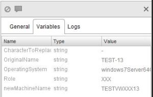
  13. When the workflow finishes, check the Variables tab on the right to confirm that the newMachineName parameter has the expected value.

    Resulting newMachineName
    Resulting newMachineName
  14. If satisfied, click “Save and close” to save your new workflow

vCAC Workflow

There are only two changes to be made from the steps outlined here.  The first is in Step 3, instead of using a variable named “PowerShellOutVar“, we’re just going to name it “OutVar” for obvious reasons.  The second change is a replacement of step 7, do this instead:

  • From the DynamicOps.VcoModel.Activities toolbox, drag “InvokeVcoWorkflow” to the designer.

    InvokeVcoWorkflow
    InvokeVcoWorkflow
  • Click the ellipsis button to  display a list of the workflows in vCO, select the workflow we made earlier (vCAC.MachineName in this case).  Note that you can filter on the Folder to make it easier to find.
  • Set the parameters
    Direction Name expression/value
    Input OriginalName vmName
    Input OperatingSystem vmwareOS
    Input Role machineRole
    Output newMachineName OutVar

    Variables & Parameters
    Variables & Parameters
  • Continue with the remainder of the steps, remembering that when you link it up in step 12, you’ve replaced “InvokePowerShell” with “InvokeVcoWorkflow

Good luck!

NSX-v and vCNS Coexistence

It may or may not be apparent, but NSX for vSphere is in many ways the next version of vCNS. In my lab, I’ve attempted to keep vCNS while adding NSX to the same vCenter server. The license key or configuration apparently overlap; if vShield Manager boots up first, NSX indicates that it’s not licensed. If NSX manager boots first, the vShield Manager states that it’s not licensed.

I did not, but should have, performed an upgrade from vCNS to NSX and now will have to add NSX Edge Gateways to replace the vShield Edges.

Migrate a VM from vCloud Director to vCloud Automation Center

First, there’s no official automated procedure for the migration yet. Here is a method to get some of your vCD-managed VMs into vCAC.

  1. Because vCD names the actual VM with an ugly UID, we want to clone the VM to a “nice” name with vSphere.  As always, make sure you have sufficient room on your storage.  The destination cluster for the clone should already be included as a compute resource in vCAC/IaaS.
  2. In the vSphere Web Client, edit the clone VM, navigate to the “vApp Options” tab and uncheck “Enable vApp Options”.  This removes the vCloud Director properties from the VM.Disable vApp options
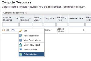
  3. Request (or wait for) an inventory data collection to run against the compute resource in vCAC.
    Request an Inventory update for the Compute Resource
    Request an Inventory update for the Compute Resource
  4. Login to vCAC as a Fabric Admin, navigate to Infrastructure|Infrastructure Organizer|Infrastructure Organizer.
  5. Click “Next” on step 1 of the Infrastructure Organizer wizardInfrastructure Organizer - Step 1
  6. On step 2, check the box beside the Compute Resource that contains the clone VM, click “Next”.Infrastructure Organizer - Step 2
  7. On step 3, ensure your compute resource is assigned to a Fabric Group and, optionally, a Cost Profile, click “Next” to continue.Infrastructure Organizer - Step 3
  8. In step 4, you’ll be presented with a list of the VMs in the compute cluster that are not managed by vCAC.  For each VM to be imported, click the pencil to edit it and assign to a Business Group.  Any VMs you do not want to import, just do not assign to a Business Group. Click “Next” when done.
  9. In step 5, you’ll edit your selected VMs to assigning them to an existing Blueprint, Reservation and Owner.  This is done so that vCAC knows how to handle the VM’s lease, resource allocation and who has access.  Next!Infrastructure Organizer - Step 5
  10. Last Step, verify how many machines will be registered.  Click Finish to complete the import.
  11. Once the VMs are imported, the owner or appropriate Business Group Manager can logon to vCAC, find the VM under his or her items and power it on from there.
  12. Lastly, once the VM’s operation is verified, the original VM in vCloud Director should be backed up and removed.

Notes

This is not intended to import a vApp into a multiple-machine blueprint or similar.  This is just for importing individual VMs into a Business Group.

I used vCloud Director v5.5.1.1 and vCloud Automation Center v6.0.1.1.

Extending vCAC IaaS to fix an annoyance

Background: When provisioning a Windows VM using the Clone Workflow and a vSphere customization specification that joins the computer to an active directory domain, the computer object is placed in the “Computers” container. I want to change that. 🙂

Solution Overview:
Modify the built-in Stub workflow to execute a Powershell script that moves the computer object based on the Business Group.

Preparation:

  1. Created a new Build Profile with the ActiveDirectoryCleanupPlugin, MiscellaneousVrmProperties, RemoteDesktopProtocolProperties and VMwareWindows2008R2_64Properties Property Sets.

    vCAC Build Profile Properties
    vCAC Build Profile Properties
  2. Created a new Windows 2008 R2 VM from a vSphere template, did not power-on. Took a snapshot
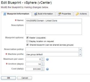
  3. Created a new shared vSphere Linked Clone Blueprint, included a customization specification that joins the machine to the domain

    vCAC Windows Blueprint Information
    vCAC Windows Blueprint Information

    vCAC Windows Blueprint Build information
    vCAC Windows Blueprint Build information
  4. Created a Business Group, Created a reservation for them, entitled the Business Group to the service and catalog item for the Windows Server
  5. Tested requesting a new machine, it was provisioned, sysprepped and joined the domain correctly. I was annoyed that the computer object was in the “Computers” container.
  6. Installed the VMware vCloud Automation Center Designer (found at https://your-vcac-server:5480/i) on the IaaS Server.
  7. Installed Active Directory module for Windows PowerShell part of RSAT on the IaaS Server

Steps

  1. We’ll need to indicate where we want the Computer Object moved to, so we’ll add that property. Since I wanted all of my Business Group’s computer objects in the same place, I added a property named targetOU to the Business Group and assigned the distinguishedName of the OU.

    targetOU property added to Business Group
    targetOU property added to Business Group
  2. Save the PS script to C:\scripts\movecomputer.ps1

    Import-Module ActiveDirectory
    write "VM Name - $vmName" | out-file c:\scripts\invoketest.txt
    write "Target OU - $targetOU" | out-file c:\scripts\invoketest.txt -Append
    Get-ADComputer $vmName | Move-ADObject -TargetPath $targetOU

    This script will write out our variables to a text file, so we can verify that they’re getting passed correctly. Then it performs the move. Please note that this will be executed by the DEM, so make sure the execution account has permissions to perform this action in AD.

  3. Launch the vCAC Designer, Load the WFStubMachineProvisioned workflow from the list
    vCAC Designer Workflows
    vCAC Designer Workflows
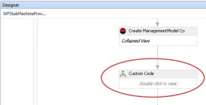
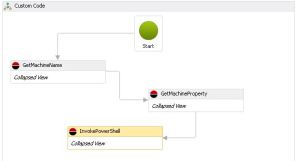
  4. In the “Machine Provisioned” try loop, locate and double-click on the “Custom-Code” item.

    Custom Code section in workflow
    Custom Code section in workflow
  5. From the toolbox, under DynamicOps.Cdk.Activities, drag the GetMachineName element into the Custom Code box
  6. From the toolbox, under DynamicOps.Cdk.Activities, also drag the GetMachineProperty and InvokePowerShell elements into the Custom Code box, near GetMachineName
  7. Drag a connection from one of the “tabs” on the Start element to the GetMachineName element, from GetMachineName to GetMachineProperty and from GetMachineProperty to InvokePowerShell

    vCAC Designer - Workflow Custom Code Wiring
    vCAC Designer – Workflow Custom Code Wiring
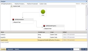
  8. While still in the Custom Code element, click “Variables” (near the bottom), click Create Variable and enter vmName for the name, leave the variable type as String. Repeat with a variable named targetOU. These are going to hold the values we want to work with through the workflow.

    Custom Code Variables
    Custom Code Variables
  9. Select the GetMachineName element. On the Properties pane to the right, enter VirtualMachineId in the MachineId field. In the MachineName field, enter vmName. Ok, so where do these come from?!
    If you click on “Arguments” while in the GetMachineName element, you’ll see two, VirtualMachineId and ExternalWorkflowId. These are standard internal values that are used in these external workflows. So, we’re providing the VirtualMachine Id GUID to the system to look up the Virtual Machine Name. The “vmName” value is the name of the variable we assigned a moment ago and the GetMachineName element enters the retrieved Name into the vmName variable.

    GetMachineName Properties
    GetMachineName Properties
  10. Now select the GetMachineProperty element and work with its properties. Just like before, set the MachineId to VirtualMachineId. Here, we want to retrieve the value in the “targetOU” property and set it in the targetOU variable. So set the PropertyValue to targetOU without quotes and the PropertyName to "targetOU" WITH QUOTES.

    GetMachineProperty Properties
    GetMachineProperty Properties
  11. Select the InvokePowerShell element. Notice there are several more properties in with this one – don’t worry, we’re only going to use a few. In my case, I chose to use a PS script instead of a one-liner. This way, I could modify the script without modifying the workflow. So, check the box labelled “IsScript” and set the CommandText to the full path of the PS script in quotes. In this case, use "C:\scripts\movecomputer.ps1".

    InvokePowerShell Properties
    InvokePowerShell Properties
  12. Our script expects two variables to be provided; $vmName and $targetOU, so click the ellipsis beside PowerShellVariables. Click Create Argument to add a new variable. Set the name to vmName, leave the direction as In and the type as String, set the value also to vmName” no quotes. Repeat for targetOU. Here, we’re telling it to create PowerShell Variables and set their values to the values of the workflow. Click Ok

    Powershell Variables
    PowerShell Variables
  13. Click “Send” to upload the modified workflow to the Model Manager. Now that we’ve created the workflow, we need to make sure it fires when we want it to.
  14. Back in vCAC Infrastructure, modify the Windows blueprint by adding a property named ExternalWFStubs.MachineProvisioned. No value needed. This way, when this shared blueprint is used by any Business Group, the computer object will be moved to
    the OU given in the Business Group’s targetOU property.

    Property Added to blueprint to call customized workflow
    Property Added to blueprint to call customized workflow

Results
When an entitled member of Business Group 1 requests a VM from the Windows 2008 R2 catalog item, the VM is correctly created as a linked clone, assigned an IP address from the network profile and its Computer Object moved as expected.

I probably should have broken this into multiple parts…

References:
I would still be twiddling my thumbs if it weren’t for the following enormously helpful bloggers:

vCAC 6.0 IaaS .NET Framework – Quick note

The Windows 2008 R2 template I was deploying the IaaS component for vCAC on already has .NET Framework 4.5.1 installed. The .NET Framework 4.5 installer downloaded from the vCAC server indicated that a newer version was installed and made no changes. However, the IaaS component installer did not complete successfully and the setup log files indicated that .NET 4.5 was not found. I had to remove 4.5.1 and replace it with the 4.5 version downloaded from the vCAC server.

TR;DR – Remove .NET FW 4.5.1, replace it with .NET FW 4.5

The vCAC 6.0.1 release notes explain that support has not been extended to .NET 4.5.1, so for now, you will have to roll back to .NET 4.5.

Use Cisco Nexus 1000V for virtual hosts in nested ESXi

The native VMware vSwitch and Distributed vSwitch do not use MAC-learning. This was removed because the vSwitches would be aware of the VMs attached to them and the MAC addresses in use. As a result, if you nest ESXi under a standard vSwitch and power-on VMs under the nested instance, those VMs will be unable to communicate because their MACs are masked by the virtual host and the vSwitch is not aware of them.

Workaround options:

  1. Enable Promiscuous mode on the vSwitch.
  2. This works but should never be used in production.  It adds a lot of unnecessary traffic and work to the physical NICs.  It makes troubleshooting difficult and is a security risk
  3. Attach your virtual hosts to a Cisco Nexus 1000V.
  4. The 1000V retains MAC-learning, so VMs on nested virtual ESXi hosts can successfully communicate because the switch learns the nested MAC addresses.
  5. If your physical servers support virtual interfaces, you can create additional “physical” interfaces and pass them through to the virtual instances.  This allows you to place the virtual hosts on the same switch as the physical hosts if you choose.  There is obviously a finite amount of virtual interfaces you can create in the service profile, but I think this is a clean, low-overhead solution for environments using Cisco UCS or HP C7000 or similar.

Conclusion

The Nexus 1000V brings back important functionality for nested ESXi environments, especially those environments that do not have access to features like virtual interfaces and service profiles.

Helpful links:

Standing Up The Cisco Nexus 1000v In Less Than 10 Minutes by Kendrick Coleman

VMware Horizon View Network Ports Illustrated pt. 2

As Carl pointed out, I left HTML Access (aka Blast) off of the first round of View network port diagrams.  So after going through the documents and making various connections while running TCPView, here’s the updated diagrams including the networks ports used by HTML Access and the Blast Secure Gateway.

Here’s the PDF

HTML Access & Blast Secure Gateway without Security Server

HTML Access Direct Connect without Security Server

HTML Access & Blast Secure Gateway with Security Server

Eww, curved, intersecting lines.

Once again, here’s the PDF

VMware Horizon View Network Ports Illustrated

I’ve recently had to attempt to describe the ports used in the various connection scenarios used by VMware View and found that a diagram really helped clear things up and have aided in producing accurate firewall rules.

A couple notes about the connections depicted though;

  • I only included v5.x. Previous versions behave differently, so use caution if you reference these in an environment where v4.x components are reused.
  • I did not depict the connection from the vCenter Server to hosts, LDAP etc. These diagrams are View-centric
  • Although the View client may connect to the View Connection Server over HTTP/TCP80, I did not depict it because we strongly prefer the HTTPS, encrypted connection.
  • Wyse MMR is not included since it is not supported on Windows 7 Virtual Desktops
  • Black arrows indicate TCP connection request and direction
  • Green arrows represent UDP traffic flow

Here’s the PDF

PCoIP with Secure Gateway on Security Server

PCoIP with Secure Gateway on Connection Server

RDP with Secure Tunnel on Connection Server

RDP with Secure Tunnel on Security Server

RDP Direct Connection without Security Server

PCoIP Direct Connection without Security Server

Once again, here’s the PDF